Raspberry Pi + Switch
I had quite some fight to get my switch finally working with my Raspberry Pi. Here’s the story about that …
Hardware
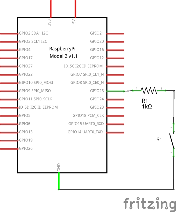
To connect a switch you will need to configure a GPIO pin as an input and then connect it through that switch to either a high signal (3.3V when using a Raspberry Pi) or a low signal (generally ground). We will use the variant connecting to ground in the following. As switches tend to have rather long cables attached this should be a better choice than to have it connect the high signal whilst connecting ground should not provide any problems due to cable lengths. We will need a GPIO pin to connect to. In the following pin 25 will be used for this.
The Basic Circuit
So the basic circuit would connect pin 25 to the one side of the switch and then connect the other side of the switch to ground. The following schematic shows this basic circuit (do not use it as such, read on!).

Adding a Current-Limiting Resistor
Now let’s first consider some safety. What if you configure the pin as an output (instead of the intended input), set it to high, and then close the switch? You will have a direct connection between +3.3V and GND, effectively creating a short-circuit and blowing up your stuff. Therefore it makes sense to include a resistor near the pin that would limit the current in this scenario.
If you now do the steps laid out above you avoid the short by having a resistor included limiting the current flow. When setup correctly the pin will still receive a low signal through the connection to ground while the switch is closed.
Adding a Pull-Up (or Pull-Down) Resistor
While the switch is open, however, the pin will not be connected to anything but the resistor, a state often called floating. As there is no defined signal on the connected lane, the input pin might pick up interference or alike and give any kind of results. To provide a high-signal while the switch is in open state we will need to provide a path to 3,3 Volts. However we do not want a short between that connection to the power source and the connection to ground and therefore need to add another resistor to the path to the power source.
Current will always flow on the path with the least resistance, so this allows us to define which path should be used. This kind of resistor is often referred to as a pull-up resistor, as it pulls the signal to the high state while the switch is not closed. In cases where you use a resistor to pull a signal to the low state it is accordingly called pull-down resistor instead. See above why a pull-up resistor might be more approriate when connecting a switch.

This circuitry should now be fail-safe in case of misconfiguration of the input pin and provides stable low/high signals depending on the state of the switch.
Software
Switches are mechanical and therefore often do not allow stable readings directly after the switch changes state. This phenomenon is called bouncing and effectively makes the signal bounce between high and low with increasing frequency before settling down on the actual state. The characteristics will vary here depending on the hardware used.
RPi.GPIO Library
In the following the Python library RPi.GPIO for the Raspberry’s GPIO pins will be used. These allow to setup the pins, manually read states from input pins or set states for output pins, as well as define a function to be called on state-changes. The latter is called edge-detection, as on the hardware-level the voltage is monitored for edges in the graph as they occur when the voltage switches from high to low. Having a function be called whenever something happens instead of constantly monitoring for changes is also reffered to as call-back.
Call-backs basically provide interrupts as they trigger on something happening. They therefore need to run threaded. This is all encapsuled in the library. A call-back function for a pin can be defined within the setup of that pin by adding according parameters. The simple setup for manual readings and the more complex with the definition of a call-back function we are actually going to use are:
1
2
3
import RPi.GPIO as GPIO
#GPIO.add_event_detect(in_pin, GPIO.BOTH)
GPIO.add_event_detect(25, GPIO.BOTH, callback=self._interrupt_pir, bouncetime=300)
On line 1 the library is imported so it can be used. Line 2 is actually commented out and only present to show the simple notation. Line 3 is the actual initialisation wit the additional parameters callback and bouncetime. The callback parameter defines the function that will be called whenever a state-change has been detected. The bouncetime parameter allows us to define a waiting-time at the same. This is used for de-bouncing the described varying readings shortly after the switch was pressed/released. Without this callback parameter the function was triggered multiple times in my setup. You might need to try around to find a value approriate to your hardware.
Call-Back Function
Now we need to define that function that is going to be called on all
state-changes. You could use GPIO.UP or GPIO.DOWN instead of GPIO.BOTH
above to limit on what kind of state changes your callback should be
called. It’s good to know that, when called, this function will be
provided with a parameter defining what pin triggered the callback. In
cases where you use several pins this is important. But let’s have
a look at a simple implementation of such a callback:
1
2
3
4
5
6
7
8
9
10
11
12
  def interrupt_switch(self, in_gpio_pin):
    """
    Interrupt function (callback) for the switch.
    """

    time.sleep(0.02)
    self.switch_open = self.myGPIO.input(in_gpio_pin)

    if (self.switch_open):
      logging.info("INTERRUPT: [Pin " + str(in_gpio_pin) + "] HIGH, switch circuit OPEN, button DOWN")
    else:
      logging.info("INTERRUPT: [Pin " + str(in_gpio_pin) + "] LOW, switch circuit CLOSED, button UP")
Line 1 defines the function named according to aboves definition. It needs to take a parameter besides the self which will indicate what pin triggered (important if you use several pins in parallel). Line 2-4 are comments. On Line 6 we manually sleep for a short period of time. Not sure why, but without this manual debounce I wasn’t able to get reliable readings. Line 7 then does the actual reading from the pin provided. Lines 9-12 output messages according to my hardware. Switches are available in different versions, so the up/down might be twisted. The code uses the logging library for the output. If you do not use that you will need to replace logging.info by print. Also this is where you put the code that should be executed in the either case.
Conclusion
Just connecting a simple switch turned out to be quite a task. However, I was new to this all, so the next time should be less hassle. Maybe this write-up is of help for some of you, too? You might need to tweak the parameters to timing (bounce option on initialisation and maybe a short sleep at the beginning of the callback). As described, I had to use both of those to get rid of multiple activations as well as unstable readings. Not sure, why setting a higher value for the bouncetime parameter doesn’t accomplish the same. Any ideas on this? Please let me know …
Also note that there are other ways to address signal-bouncing. For example that can be addressed by using a more sophisticated circuit as well. So it’s not like this is the only truth out there. It’s just what I hacked together to make it work.
ClearNet-Links:
- http://www.dummies.com/computers/raspberry-pi/recognizing-and-coping-with-contact-bounce-on-the-raspberry-pi/
Tagged: raspberrypi, switch, bouncing, pull-up-resistor, pull-down-resistor, and current-limiting-resistor